BIMXtra helps Kier to manage a complex car park redevelopment
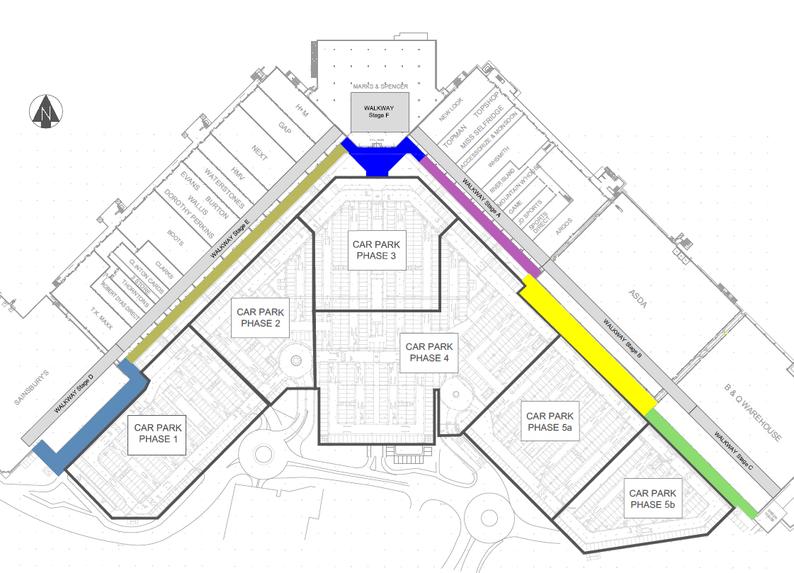
Kier has been contracted to demolish and rebuild the car park and associated walkways at Castlepoint shopping centre in Bournemouth. The complex programme of works will take place in six phases, as the shops need to remain open for the majority of time during the work and there needs to be minimum disruption to the parking for shoppers.
Another complication to this project is that existing assets such as signage, vehicle impact bollards, balustrades and street lighting are being kept, refurbished where necessary and reinstalled. There are 1,200 of these in Phase 1 alone. Many of these were cut to size and so are unique and need to be replaced in the exact position that they came from.
The team is using BIMXtra to digitally manage and track all project information ensuring that they are able to keep accurate records across the whole project lifecycle. They received one 3D model of the site from the consultants, which they used as the basis for all further modelling and information gathering within BIMXtra.
Scheduling
Sequencing and logistics are crucial on this job, as is spatial planning to minimise disruption, while ensuring works can be carried out as planned. As such, analysing static 3D models isn’t always effective in working out where there could be issues.
Within BIMXtra the team was able to input the programme information against the model and carry out 4D sequencing and simulation. This enabled them to see any errors or clashes. For example, one of the walkway demolitions was simulated in 4D. This simulation became a vital tool in meetings when discussing the walkway reconstruction, aiding talks about hoarding layouts, types of plant and material storage when working in the tight space. It helped the team think about issues that hadn’t occurred to them and highlighted a number of problems with the initial temporary works design.
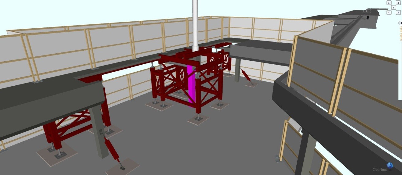
The image on the left shows the first temporary works design. The concrete column highlighted in pink needs to be removed without damaging the existing foundation but at the same times, the canopy column above (shown in white) will be supported by temporary steelwork. While the design appeared to work when viewed in 2D, once simulated in 3D it was clear that there would not be enough space to cut the column and lift it out.
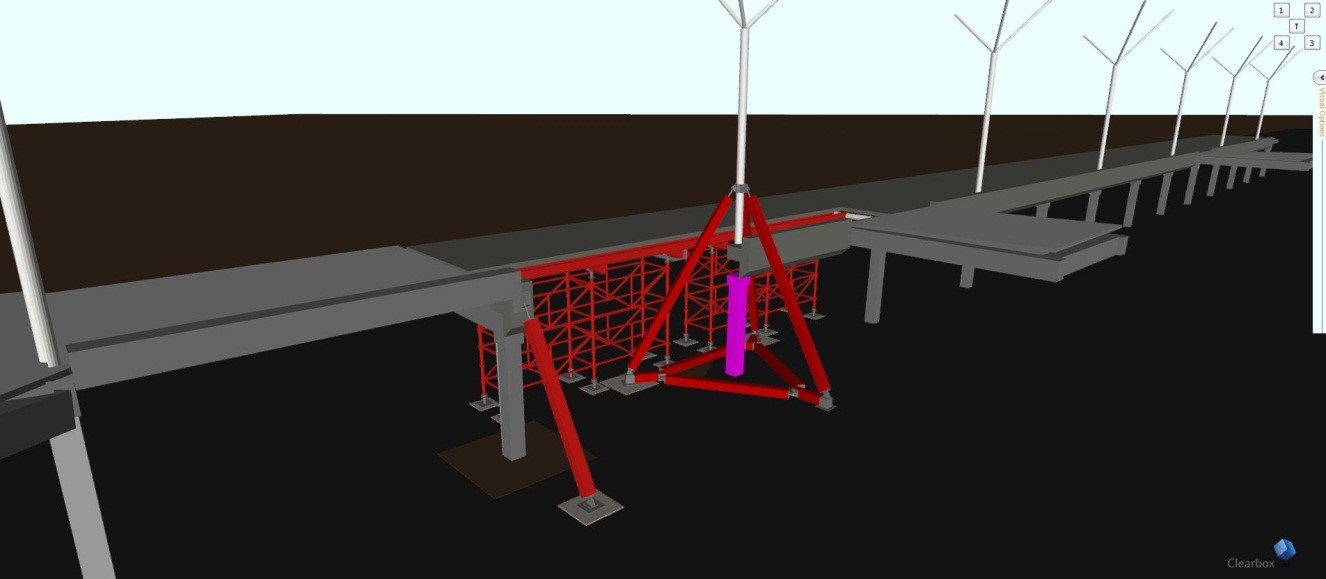
When this was shown to the temporary works designer, they immediately understood the issue and came back with a new design (picture to the right), which allowed for more space to work around the column and lift it out by crane. This problem may have been overlooked for some time had it not been for the simulation of the demolition process.
Commenting on the 4D simulation, Jack Holloway said, “We have simulated the construction sequence of our model on a week by week basis. Just doing this alone has enabled us to foresee many issues. This simulation can be formatted over whatever timeframe you desire. For example, we broke down a section of our construction sequence to a day by day programme due to some complex temporary works. From this we could see that the temporary works were inappropriate and required re-evaluation. We also have a very tight site and from carrying out the sequencing we can see where we have room to store materials at various stages of the project. The team has found this very useful. On a personal note, I also found that by simulating the model in great detail, it required evaluating the programme in a greater depth and this brought up flaws in the programme that may not have been picked up before. Just having this tool alone will massively benefit any project.”
Managing assets
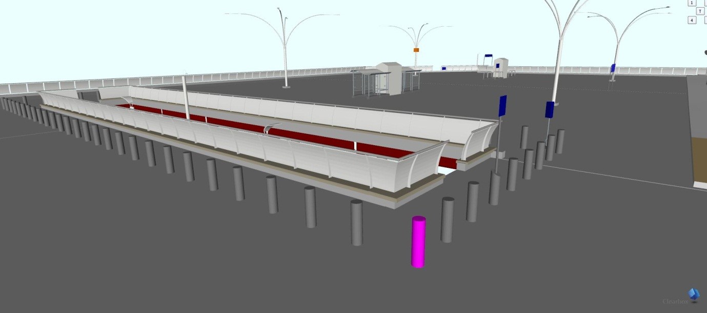
The Kier team has created models of every asset for Phase 1, created an asset tagging model, and added it to the original 3D model. They will repeat this for each phase.
To do this, the assets themselves first had to be surveyed. For items such as the vehicle impact bollards, lighting columns and signage, this was done by surveying their location with an Electronic Distance Meter and then exporting the data as a .DXF file. This could then be edited in AutoCAD and, once the drawing had all the required information, it was imported into Revit and overlaid on top of the original car park model created by the consultant. This gave a reference point on the model for each asset, allowing them to be placed accurately. Items such as the balustrade surrounding the void were surveyed by measuring the length of each section.
From there, individual families for each element were modelled in Revit and then placed in the appropriate position to build up the model. This was then uploaded to BIMXtra.
While out on site, the model can be viewed through Insight on tablet computers. Individual elements can then be selected and a form attached to that item in the model. The form contains information such as item condition and storage location – photographs of the item are also taken using the tablet and attached to the form. The form is then uploaded and stored in BIMXtra. These QA forms provide excellent records for reinstallation and are used against items such as drainage, tarmac and steel installations.
The forms are context sensitive, so the user only sees what is relevant to them at that stage of the project. Once they have been signed off the data cannot be edited, which means that accurate records are kept for each stage of the process.
The team is also attaching a barcode label to every asset. This barcode is then scanned and automatically linked through the form to the relative element in the model. Once the asset has been removed and stored, the barcode can be scanned again, highlighting the element in the model and indicating the location where the item has to be reinstated. All the information uploaded in the form can also be checked to ensure no damage has been done to the item in removal / transit.
Benefits
Kier has found that, thanks to the detail stored about the project in BIMXtra and the visualisation available to them through Insight, the simulation and visualisations are extremely useful for the team, engineers, foremen, sub-contractors and clients.
Jack added, “A picture speaks 1,000 words, and when it is in 3D, with a date, it is even better.”
The team is also saving a massive amount of time managing the assets by tagging and logging them digitally. It ensures all the information is kept in one place and avoids having piles of paperwork, hundreds of folders of photographs and confusing naming systems. It also provides an easy to understand visual representation of the car park assets, so you can quickly find the asset you want and have all the information about that item instantly.
More to be gained
Each phase of the demolition and rebuild will take approximately a year.
The team is having a dust, noise and vibration sensor installed onsite – with future developments on BIMXtra they will be able to analyse trends in the data on this to ensure they’re meeting their requirements. Alerts can be set up if levels become too high.
Topography from OS has also been imported into BIMXtra’s viewing engine, Insight. This enables the site to be viewed in its geographical context, which the team believe will help when scheduling deliveries to site.
The team will also undertake work packaging and, with the detailed information they have recorded on the project, this will be easy through BIMXtra and ensure the supply chain is fully engaged and has all of the information it needs to successfully complete the work.